APM 2.8 Build Guide
Research and development platform with autonomous flight capabilities, GPS waypoint missions, and AI integration. Perfect for advanced users exploring automated flight systems and autonomous AI missions.
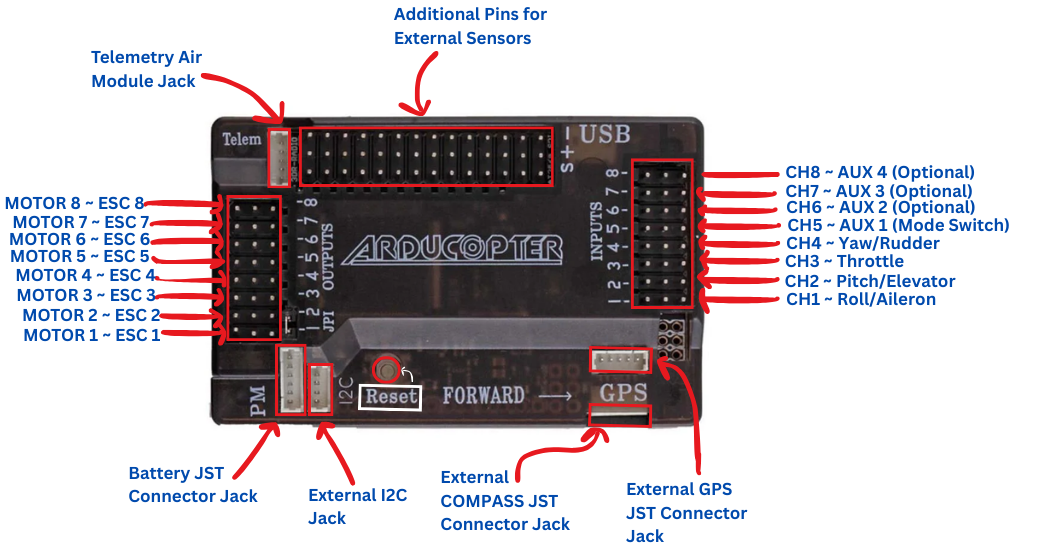
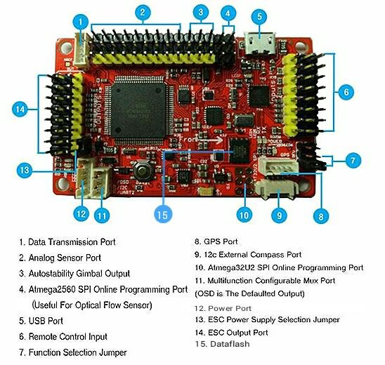
APM 2.8 Pinout
Understanding the advanced connection layout
Output Channels
- CH1-CH8: Motor/Servo outputs
- Pin Order: Signal, +5V, Ground
- Quad X: Use CH1-CH4
Input Channels
- CH1-CH8: Receiver inputs
- PPM Sum: Single cable option
- Powered: Via receiver rail
GPS & Compass
- GPS Port: NEO-6M/7M connection
- I2C Port: Compass module
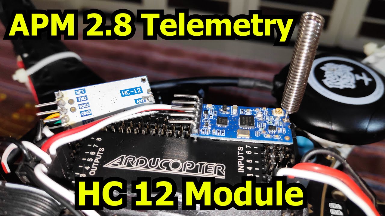
- Telemetry: 433/915MHz radio
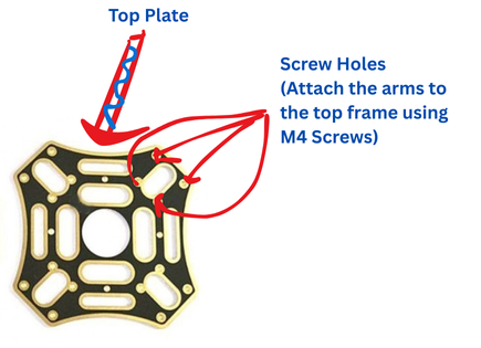
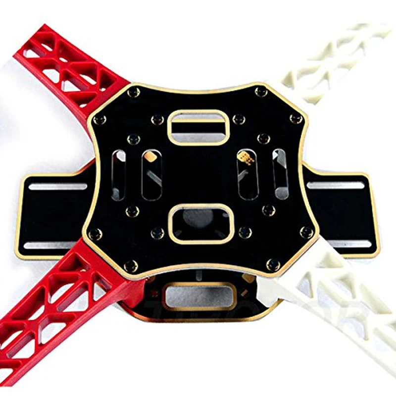
F450 Drone Frame Assembly
Building the structural foundation of your drone

Bottom Plate & Power Distribution
Install the ESCs and power distribution board on the bottom plate. Solder the XT60 female connector for battery connection. Ensure proper wire routing for clean cable management.
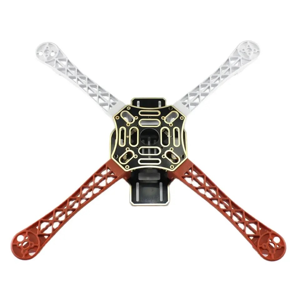
Arm Installation
Attach the four arms to the bottom plate using M3 screws and nuts. Ensure arms are firmly secured with colored indicators for front/rear identification (red arms indicate front).
Motor Mounting
Mount BLDC motors to each arm using M3 screws. Pay attention to motor rotation direction (2 CW, 2 CCW). For APM, motor order is critical - refer to APM motor layout diagram.
Top Plate Assembly
Install APM flight controller, receiver, and GPS module. Secure top plate with standoffs and screws. Mount GPS on a mast for best signal reception.
Inside APM 2.8 Flight Controller
Understanding the onboard components
Processor
ATmega2560 - 16MHz 8-bit processor with 256KB flash memory for complex flight operations
IMU Sensors
MPU-6000 - 3-axis gyroscope and accelerometer for precise motion detection
Barometer
MS5611 - High-precision barometric pressure sensor for altitude hold
Compass
HMC5883L - 3-axis magnetometer for accurate heading information
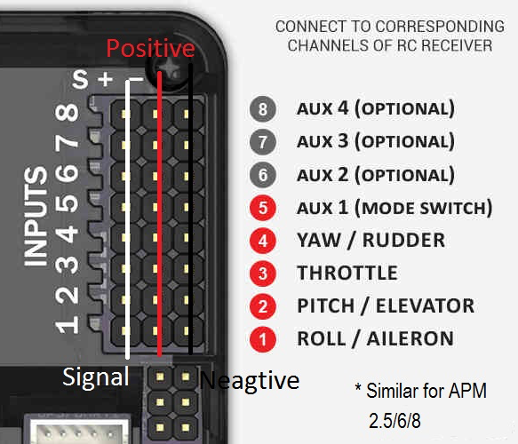
APM 2.8 Receiver Connection
Connecting FlySky iA6 receiver
APM 2.8 Complete Wiring Diagram
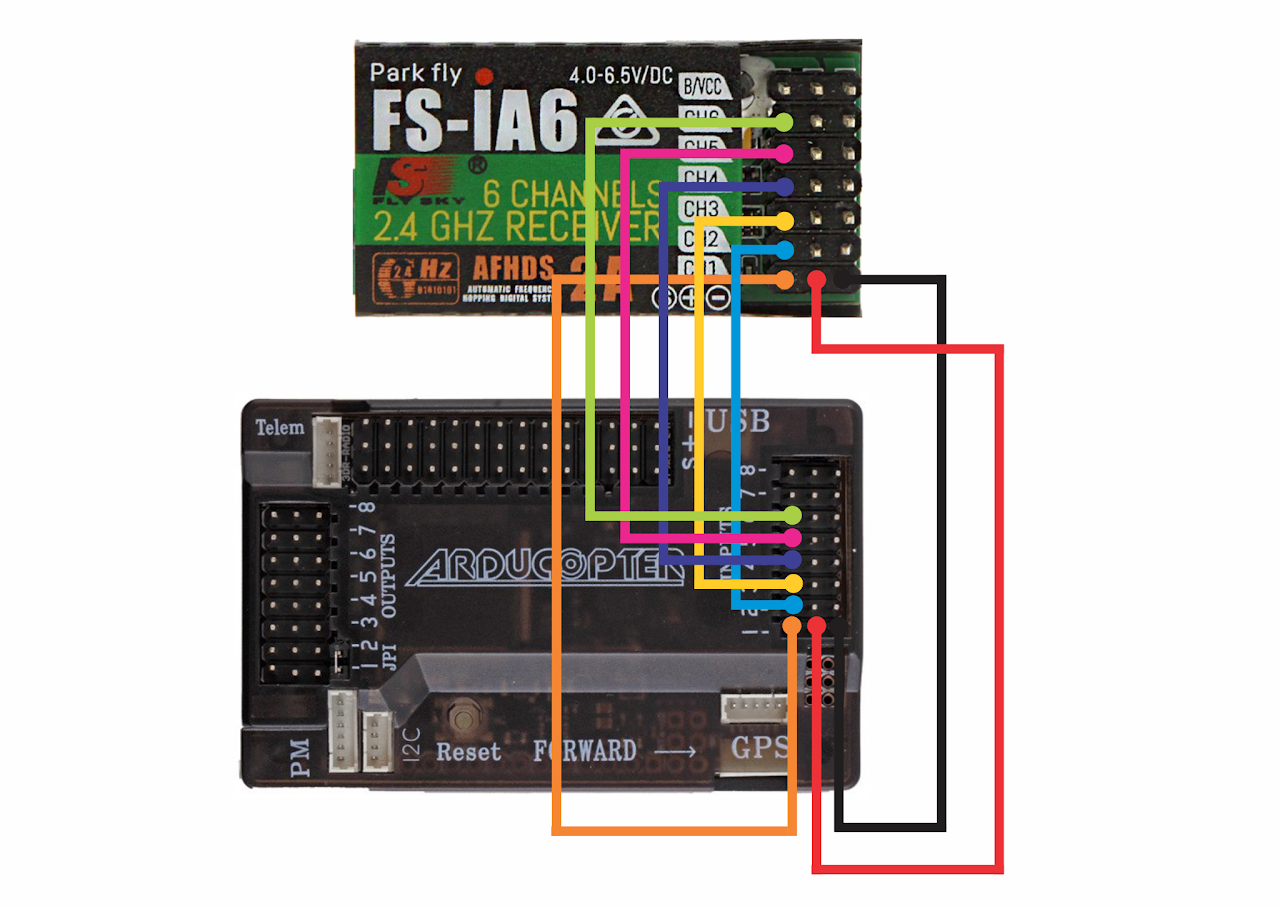
Power Flow: Battery → PDB → ESCs → Motors | APM powered via OUTPUT rail
Important: APM 2.8 requires 5V power from ESC BEC on OUTPUT side
Channel Mapping
Connect receiver channels to APM input:
- CH1: Aileron (Roll)
- CH2: Elevator (Pitch)
- CH3: Throttle
- CH4: Rudder (Yaw)
- CH5-6: Flight modes/AUX
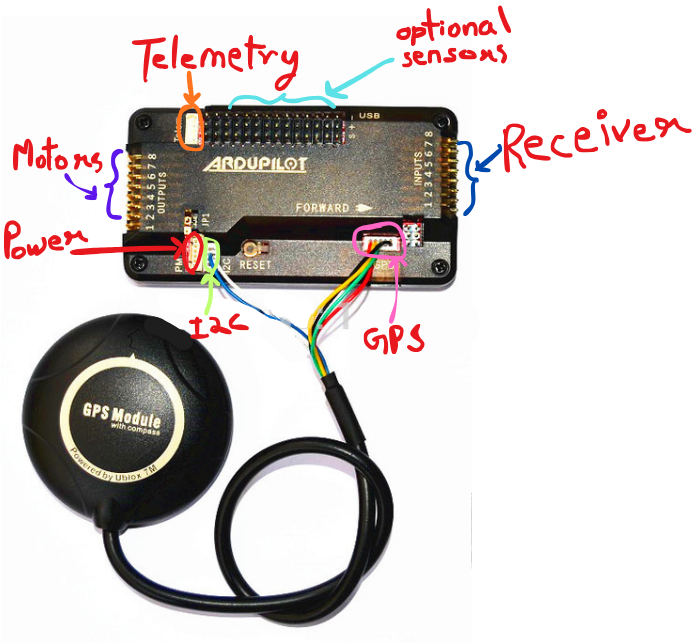
GPS & Compass Setup
NEO-7M GPS module connection:
- GPS Port: Connect GPS cable
- I2C Port: Connect compass cable
- Mounting: Away from interference
- Arrow: Points forward
APM 2.8 Detailed Wiring Guide
APM 2.8 Power Connection:
- Γ£ô APM is powered from OUTPUT rail (not INPUT)
- Γ£ô Connect ONE ESC with BEC to OUTPUT rail for 5V power
- Γ£ô Remove BEC from other 3 ESCs to avoid conflicts
- Γ£ô Never connect LiPo battery directly to APM power input
Receiver to APM Connections:
- ✓ RX CH1 (Roll) → APM INPUT CH1
- ✓ RX CH2 (Pitch) → APM INPUT CH2
- ✓ RX CH3 (Throttle) → APM INPUT CH3
- ✓ RX CH4 (Yaw) → APM INPUT CH4
- ✓ RX CH5/6 (Flight Modes) → APM INPUT CH5/6
- Γ£ô Receiver gets power from APM INPUT rail
ESC to APM OUTPUT Connections:
- ✓ ESC 1 signal → APM OUTPUT CH1 (Front Right Motor)
- ✓ ESC 2 signal → APM OUTPUT CH2 (Rear Left Motor)
- ✓ ESC 3 signal → APM OUTPUT CH3 (Front Left Motor)
- ✓ ESC 4 signal → APM OUTPUT CH4 (Rear Right Motor)
- Γ£ô Motor order differs from KK2.1.5 - check documentation!
GPS & Compass Connections:
- ✓ GPS module → GPS port (6-pin connector)
- ✓ Compass module → I2C port
- Γ£ô Mount GPS away from ESCs and power wires
- Γ£ô GPS antenna arrow points forward
Note: APM 2.8 requires Mission Planner software for configuration. Download from ardupilot.org/planner
Power Module Connection (Optional)
Enabling battery monitoring and telemetry features
Power Module Overview
The power module is optional but highly recommended for advanced features. Your drone will fly without it, but you'll miss valuable telemetry data and battery monitoring capabilities.
What It Provides
- Current Draw: Real-time amps consumption
- Battery Voltage: Live voltage monitoring
- Battery Percentage: Remaining capacity
- Idle Current: Ground power consumption
Connection Points
- Battery Input: XT60 from LiPo battery
- Power Output: To PDB/ESCs (XT60)
- 6-Pin Connector: To APM 2.8 power port
- Voltage Rating: 2-6S LiPo compatible
Telemetry Features
- Battery Failsafe: Auto-return on low battery
- Current Logging: Flight data recording
- OSD Display: Live voltage/current on FPV
- Mission Planner: Real-time battery stats
Important Notes
Required for: Battery failsafe, current logging, telemetry radio battery monitoring, and Mission Planner real-time battery data.
Not Required for: Basic flight operation. Your drone will fly normally using BEC power from ESCs without the power module.
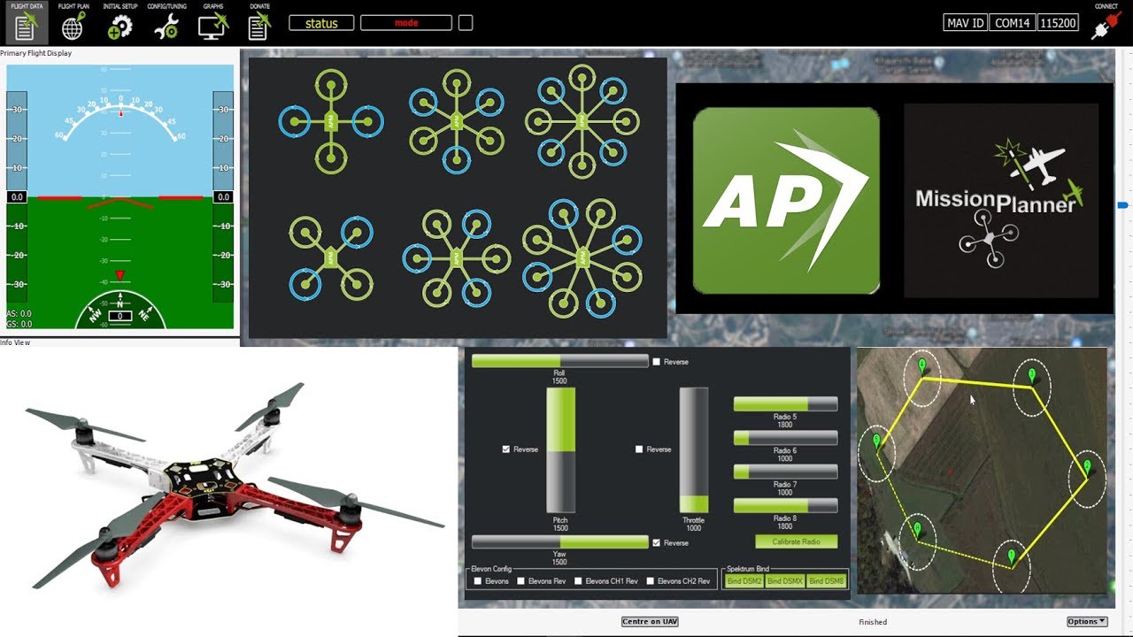
Mission Planner Configuration
Software setup for APM 2.8
Install Software
Download and install Mission Planner on your PC
Connect APM
Connect APM to PC via USB cable
Flash Firmware
Install ArduCopter firmware for quadcopter
Calibrate Sensors
Run accelerometer, compass, and radio calibration
Configure Parameters
Set frame type, flight modes, and failsafe
Pre-Flight Check
Verify all sensors and controls before flight
Assembly Videos
Watch APM 2.8 drone assembly walkthroughs
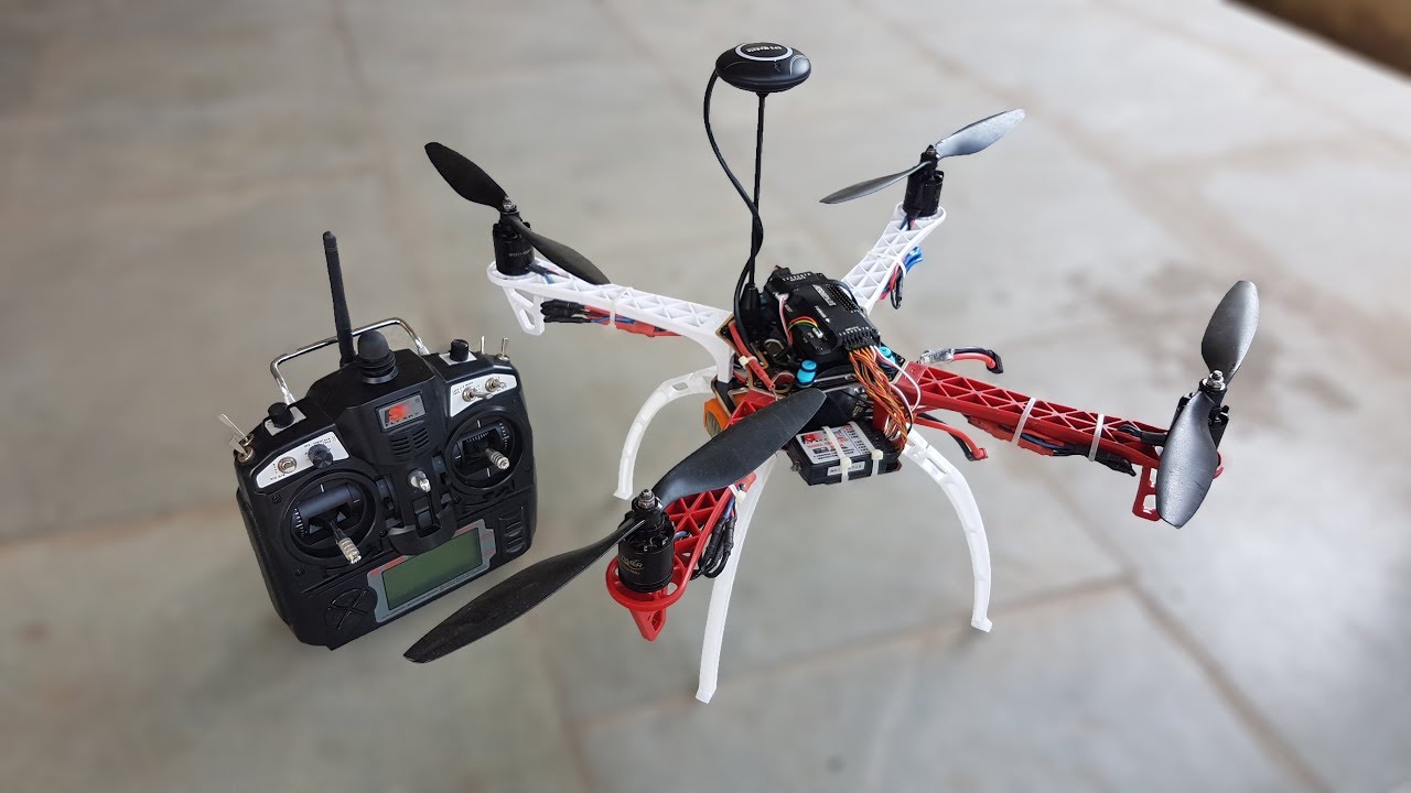
APM 2.8 Assembly Tutorial
Watch Tutorial